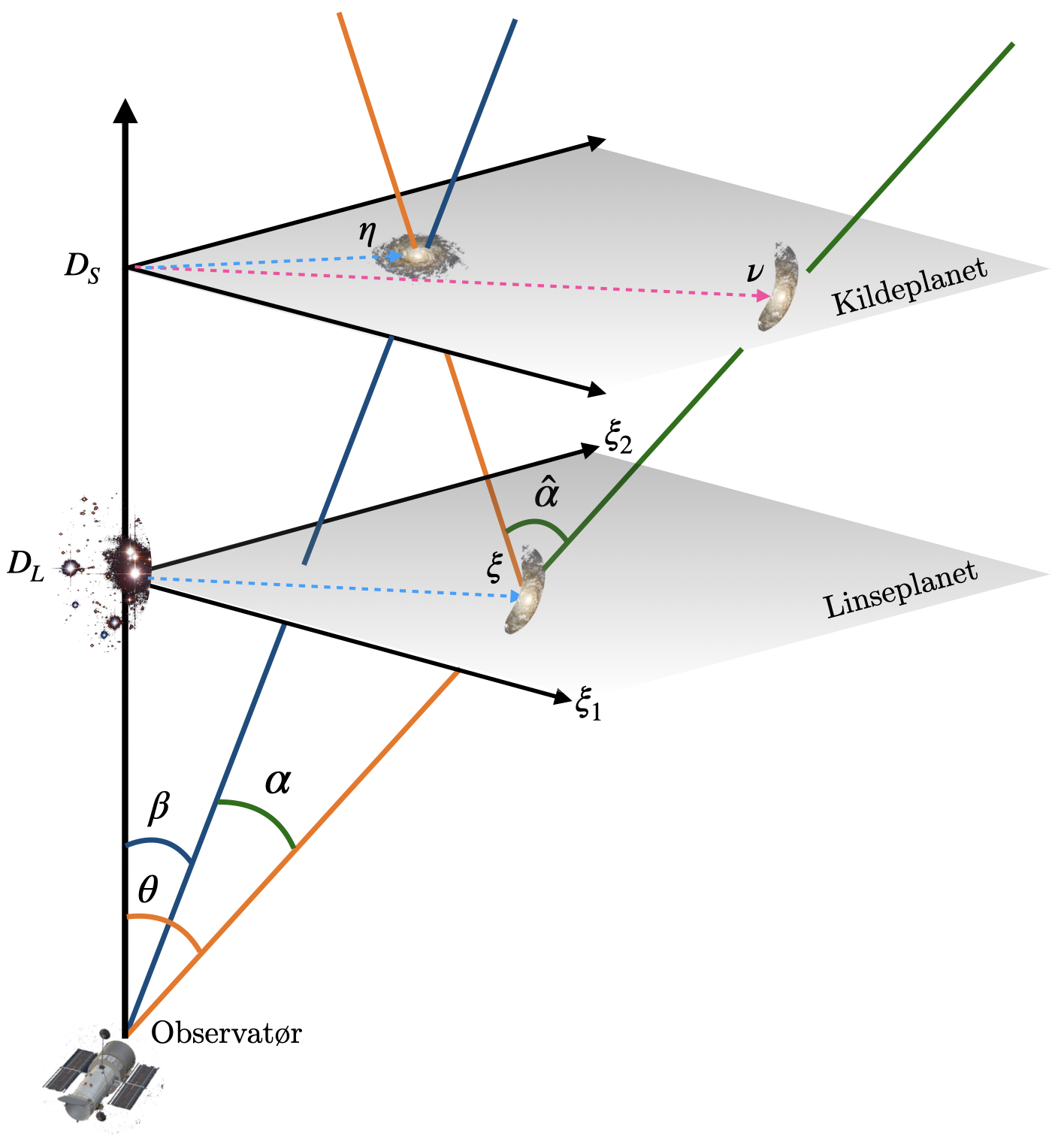
We assume a flat sky and a thin lens, which means the lens is
concentrated in one plane, orthogonal on the line of sight, with
no extension in depth. We call this the lens plane L.
Similarly, the source that we observe through the lens, is concentrated
in a parallel plane, called the source plane S.
The distances to the lens and source planes are denoted
DL and DS respectively.
The optical axis is the line from the observer through the lens.
We consider a single source point at η in S.
The apparent position, as seen by the observer, is at ν and
The deflection is most easily described in terms of angles, so
we define β and θ as the angles between
the optical axis and respectively
η and ν
(cf. figure).
The deflection angle α^ is the angle between
the actual and apparent source in the source plane as seen
from the apparent image in the lens plane.
With the flat sky approximation, the angles are related to
lengths in the lens plane by a factor of DL, so that
Under the flat sky assumption,
Eq. (6) and Eq. (7) are equivalent.
It is this latter equation that we shall take to be our constitutive relation. But before
we get there, let us also introduce the standard way of normalizing.
Leaving the angular co-ordinates for a bit,
it is customary to normalise the raytrace equation
(6),
using a constant factor ξ0.
This gives the following entities, following Kormann et al. (1994),
In addition to the previously mentioned (cosmological) distances DL, DS and DLS we must thus
find a proper length scale ξ0 from which we normalize everything else. In Schneider et al. (1999),
Kormann et al. (1994), and other standard sources one typically takes ξ0
to be the so-called Einstein radius. This is the radius at which
a spherically symmetric lens will produce a ring (so-called Einstein ring)
whenever the source is directly behind
the lens, along the optical axis.
In normalised coordinates the ray-trace equation
Eq. (6) reads
which also explains the particular definition of α: it makes the normalized
version of the ray-trace equation look very nice and tidy. The normalisation presented above is however
somewhat different from the one we shall prefer in this work,
where we shall prefer to work in angular coordinates,
such as the ones given in Eq. (7).
In the sections to follow, such coordinates will therefore be our focus.
Considering a thin lens, it is customary to define the lens potential as the projection of the 3D gravitaitonal lens
potential down on the lens plane. Such a simplification is typically warranted,
due to DL≫ξ0.
To connect with SEF1999 and other standard literature we will start by defining the lensing potential so that its gradient is the so-called reduced
deflection angle a
the gradient of ψ, i.e.
This final equation shall be taken as motivation to redefine the standard lensing potential
ever so slightly. Let ψ be the usual lensing potential. Then we define
Refering to two-dimensional points we will need both Cartesian
and Polar co-ordinates.
For the apparent position θ we will write (θ1,θ2)
for the Cartesian co-ordinates, and (θ,ϕ) for the polar
co-ordinates.
For β we will write
(β1,β2) and (β,ϕβ) respectively.
This is seen because DSα and DLSα^ are the lengths
of arcs between the actual and apparent source, and for small
angles they are both approximately equal to the straight line
ΔηS.